

IEC 60598-1 Standard
Luminaires - Part 1: General Requirements
Within the scope of the 2014/35 / EU LVD (Low Voltage Directive) directive, TS EN 60598-1 standard covers the general LVD test related to the luminaires working with supply voltages up to 1000 V combined with electric light sources. Relevant tests and rules in this standard include classification, marking, mechanical construction, electrical construction and photobiological safety. TS EN 60598-1 standard is the main standard of LVD safety tests / LVD test of luminaires.
As LVT Test Laboratories , We carry out LVD safety tests / LVD test within the scope of IEC 60598-1 standard in our laboratory accredited by TÜRKAK.
We carry out the following LVD test within the scope of IEC 60598-1 standard;
1) Classification of Luminaires
1.1)Classification according to type of protection against electric shock
Luminaires must have one of the following classes according to protection against electric shock:
Class I, Class II, Class III.
1.2) Classification according to degree of protection against ingress of dust, solid
objects and moisture
Luminaires shall be classified in accordance with the "IP number" system of classification
described in IEC 60529.
1.3) Classification according to material of supporting surface for which the luminaire
is designed
Luminaires shall be classified according to whether they are suitable for direct mounting on normally flammable surfaces or are only suitable for mounting on non-combustible surfaces as
follows:
- Luminaires suitable for direct mounting on normally flammable surfaces
- Luminaires not suitable for direct mounting on normally flammable surfaces
1.4) Classification according to the circumstances of use
– Normal use
– Rough service
2) Marking
The following information shall be distinctly and durably marked on the luminaire
a) Marking to be observed when replacing lamps or other replaceable components, shall be
visible on the outside of the luminaire (except the mounting side) or behind a cover which is
removed during lamp or other component replacement and with the lamp removed.
b) Marking to be observed during installation shall be visible during installation on the outside
of the luminaire or behind a cover or part which is removed during installation.
c) Marking to be observed after installation shall be visible with the luminaire assembled and
installed as for normal use and with the lamp in place.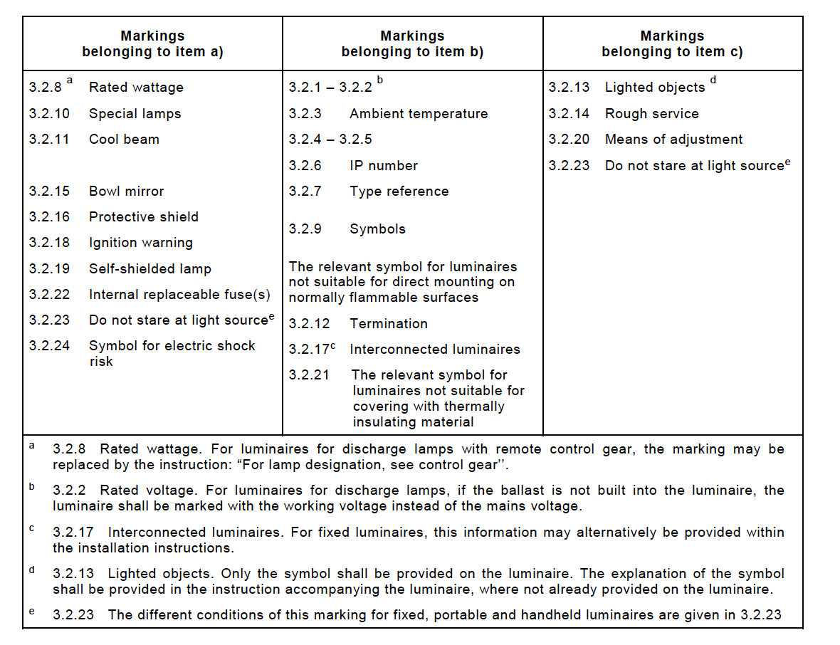
2.1 Mark of origin
2.2 Rated voltage as Volt
2.3 The rated maximum ambient temperature ta, if other than 25 °C
2.4 Symbol for class II luminaires where applicable
2.5 Symbol for class III luminaires where applicable
2.6 Marking (if applicable) with IP numbers for degree of protection against ingress of dust, solid objects and moisture
2.7 Maker's model number or type reference.
2.8 Rated wattage or the designation as indicated on the lamp data sheet of the type or types of lamp for which the luminaire is designed. Where the lamp wattage alone is insufficient, the number of lamps and the type shall also be given.
2.9 Where applicable, the relevant symbol for luminaires not suitable for direct mounting on normally flammable surfaces.
2.10 Information concerning special lamps, if applicable.
2.11 Symbol (see Figure 1), if applicable, for luminaires for lamps of similar shape to "cool beam" lamps but where the use of a dichroic reflectorized "cool beam" lamp might impair safety.
2.12 Except for type Z attachments, terminations shall be marked to identify live, neutral and earth in case of connection of the luminaire to the supply mains to ensure safe and satisfactory operation.
2.13 Symbol for minimum distance from lighted objects, if applicable, for luminaires which might otherwise overheat the lighted objects due to, for example, the applied lamp type, the shape of the reflector, the adjustability of the mounting means or the location of mounting as indicated in the installations instructions.
2.14 Symbol (see Figure 1), if applicable, for rough service luminaires.
2.15 Symbol (see Figure 1), if applicable, for luminaires which are designed for use with bowl mirror lamps.
2.16 Luminaires incorporating a protective shield shall be marked either with:
• "Replace any cracked protective shield", or
• the symbol (see Figure 1).
2.17 The maximum number of luminaires that may be interconnected or the maximum total current that may be drawn by means of couplers provided for looping-in connection to the mains supply. For fixed luminaires, this information may alternatively be provided within the installation instructions.
2.18 A warning symbol or notice for luminaires with ignitors intended for use with doubleended high pressure discharge lamps and luminaires with double-capped Fa8 tubular lamps if the voltage measured according to Figure 26 exceeds 34 V peak.
2.19 Symbol (see Figure 1) for luminaires which are designed to be used only with self-shielded tungsten halogen lamps or self-shielded metal halide lamps.
2.20 Where necessary, the means of adjustment where not obvious, needs to be identified.
2.21 The relevant symbol (see Figure 1) for luminaires not suitable for covering with thermally insulated material.
2.22 Symbol (see Figure 1) if applicable, for luminaires with internal replaceable fuses.
2.23 Warning symbol “Do not stare at the operating light source” (see Figure 1) for portable and handheld luminaires that have been classified as having a threshold illuminance Ethr in accordance with IEC/TR 62778.
2.24 Where required for protection against electric shock, covers fixed over non-user replaceable light sources shall be marked with the ‘caution, risk of electric shock’ symbol given by IEC 60417-6042 (2011-11).
3) İlave Bilgiler
In addition to the above marking, all details which are necessary to ensure proper installation, use and maintenance shall be given either on the luminaire, semi-luminaire or on built-in ballasts or in the manufacturer's instructions provided with the luminaire for instance:
3.1 For combination luminaires, the permissible ambient temperature, the class of protection or the protection against ingress of dust, solid objects and moisture of an alternative part if not at least equal to that of the basic luminaire.
3.2 Nominal frequency in hertz.
3.3 Operating temperatures:
a) The rated maximum operating temperature (of a winding) tw in degrees Celsius.
b) The rated maximum operating temperature (of a capacitor) tc in degrees Celsius.
c) The maximum temperature to which the insulation of supply cables and interconnecting cables will be subjected within the luminaire under the most unfavourable conditions of normal operation, if in excess of 90 °C (see footnote c to Table 12.2 relating to unsleeved fixed wiring). The symbol to indicate this requirement is given in Figure 1.
d) Spacing requirements to be observed during installation.
3.4 In case a luminaire is only suitable for direct mounting on non-combustible surfaces and the relevant symbol (see Figure 1) is not applied, a warning notice shall be attached to the luminaire or given in the manufacturer’s instructions explaining that the luminaire can under no circumstances be mounted on normally flammable surfaces.
3.5 A wiring diagram, except where the luminaire is suitable for direct connection to the mains supply.
3.6 Special conditions for which the luminaire, including the ballast, is suitable, for instance, whether or not the luminaire is intended for looping-in.
3.7 Luminaires provided with metal halide lamps shall, if applicable, be provided with the following warning notice: “The luminaire shall only be used complete with its protective shield”.
3.8 The manufacturer of semi-luminaires shall supply information on limitations of use of such devices, particularly where overheating may be caused by the position or thermal distribution of the replaceable light source being different from the light sources they will replace.
3.9 In addition, the manufacturer shall be prepared to supply information on the power factor and the supply current.
3.10 Suitability for use "indoors" including the related ambient temperature.
3.11 For luminaires using remote control gear, the range of lamps for which the luminaire is designed.
3.12 For clip-mounted luminaires, a warning when the luminaire is not suitable for mounting on tubular material.
3.13 The manufacturer shall provide the specifications of all protective shields.
3.14 Where necessary for correct operation, the luminaire shall be marked with the symbol for nature of supply (see Figure 1).
3.15 The rated current at rated voltage shall be declared by the manufacturer for any socket outlet incorporated in the luminaire, if less than the rated value.
3.16 The information about rough service luminaires concerning:
– the connection to IPX4 rated socket outlets;
– the correct mounting taking into account the temporary installation;
– the correct fixing to a stand, and also where the stand is not supplied with the luminaire, the maximum height of a possible stand, and its required stability by the indication of the number and minimum length of the legs.
3.17 For luminaires with type X, Y or Z attachments, the mounting instructions shall contain
the substance of the following information.
– For type X attachments having a specially prepared cord:
if the external flexible cable or cord of this luminaire is damaged, it shall be replaced by a special cord or cord exclusively available from the manufacturer or his service agent.
– For type Y attachments:
if the external flexible cable or cord of this luminaire is damaged, it shall be exclusively replaced by the manufacturer or his service agent or a similar qualified person in order to
avoid a hazard.
– For type Z attachments:
the external flexible cable or cord of this luminaire cannot be replaced; if the cord is damaged, the luminaire shall be destroyed.
3.18 Luminaires which are other than ordinary, provided with a PVC supply cord, shall be provided with information about the intended use, i.e. “For indoor use only”.
3.19 For luminaires which generate a protective conductor current greater than 10 mA and intended for permanent connection, the protective conductor current shall be clearly stated in the manufacturers’ instructions.
3.20 Wall mounted, settable and adjustable luminaires not intended to be mounted within arms reach shall be provided with information to advise their correct installation, i.e. “Only to be installed outside arms reach”.
3.21 Luminaires with non replaceable and non-user replaceable light source, the instruction sheet shall contain the substance of the following information:
– For non replacable lightsources:
"The light source of this luminaire is not replaceable; when the light source reaches its end of life the whole luminaire shall be replaced"
– For non-user replaceable light sources:
"The light source contained in this luminaire shall only be replaced by the manufacturer or his service agent or a similar qualified person."
Caution, risk of electric shock (Source: IEC 60417-6042 (2011-11))
3.22 For controllable luminaires the classification of insulation that has been maintained between LV supply and control conductors shall be provided. E.g. basic insulation, reinforced insulation.
3.101 Where the terminal block with the armature is not provided, the following statement should be included on the packaging:
“The terminal block is not included. It may be necessary to seek advice from a qualified person to make the installation. ”
Afterwards, the durability test is applied to the markings. The durability of the marking is checked by examining the markings by gently rubbing the markings with a cloth soaked in water for 15 s and then drying them out with a cloth dipped in petroleum ether for an additional 15 s. After the experiment, the marking should be readable, the marking labels should not be easily removed and there should be no creasing in these labels.
4) Construction
This section specifies general constructional requirements for luminaires.
5) External and Internal Wiring
This section specifies general requirements for the electrical connections to a supply and for
the internal wiring of luminaires.
6) Provision for Earthing
Metal parts of class I luminaires which are accessible when the luminaire has been mounted, or is opened for replacement of a replaceable light source or replaceable starter or for cleaning purposes, and which may become live in the event of an insulation fault, shall be permanently and reliably connected to an earthing terminal or earthing contact.
Metal parts screened from live parts by metal parts which are connected to the earthing terminal or earthing contact, and metal parts separated from live parts by double insulation or by reinforced insulation, are not, for the purpose of this requirement, regarded as likely to become live in the event of an insulation fault.
7) Protection Against Electric Shock
Luminaires shall be so constructed that their live parts are not accessible when the luminaire has been installed and wired as in normal use, and when it is opened as necessary for replacing replaceable light sources or (replaceable) starters, even if the operation cannot be achieved by hand. Basic insulated parts shall not be used on the outer surface of the luminaire without appropriate protection against accidental contact.
Where a protective cover is used over a non-user replaceable light source in accordance with Clause 4.30, the cover shall be left in place during the tests and inspections detailed by this section.
No access to live parts with the standard test finger is permitted when the luminaire has been installed and/or assembled for normal use and, in addition, under the same conditions:
– for portable, settable and adjustable luminaires, no access to basic insulated parts with the standard test finger is permitted, and
– for other types of luminaires, there shall be no access to basic insulated parts from the outside of the luminaire by means of a Ø,50 mm probe according to Figure 1 in
8) Resistance to Dust , Solid Objects and Moisture
8.1 This section specifies the requirements and tests for luminaires classified as resistant to dust, solid objects and moisture in accordance with Section 2, including ordinary luminaires.
8.2 The enclosure of a luminaire shall provide the degree of protection against ingress of dust, solid objects and moisture in accordance with the classification of the luminaire and the IP number marked on the luminaire.
9) Insulation resistance and Electric Strength , Touch Current and Protective Conductor Current
This section specifies requirements and tests for the insulation resistance, electric strength, touch current and protective conductor current of luminaires.
9.1 Yalıtım Direnci
The insulation resistance is measured with a DC voltage of approximately 500 V 1 minute after the voltage is applied.The insulation resistance must be above 2MΩ.
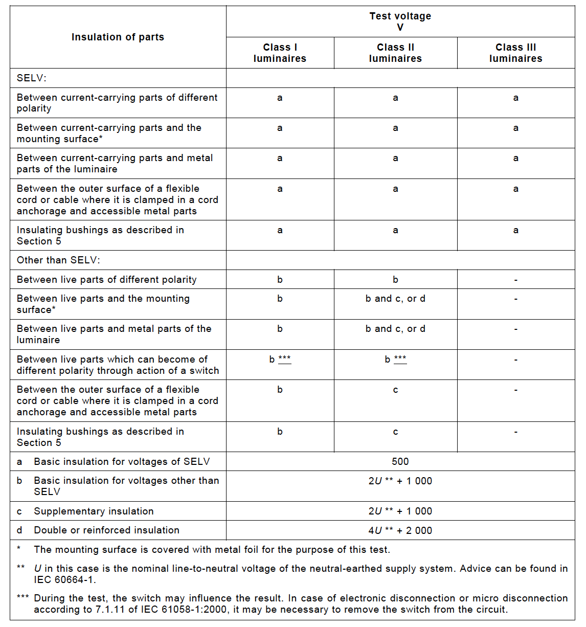
9.2 Elektriksel Dayanım
A voltage of substantially sine-wave form, with a frequency of 50 Hz or 60 Hz and the value specified in Table 10.2, shall be applied for 1 min across the insulation shown in that table.Initially, no more than half the prescribed voltage shall be applied, it is then raised gradually to the full value.
For the high-voltage transformer used for the test, when the output terminals are short-circuited after the output voltage has been adjusted to the appropriate test voltage, the output current shall be at least 200 mA. The overcurrent relay shall not trip when the output current is less than 100 mA.
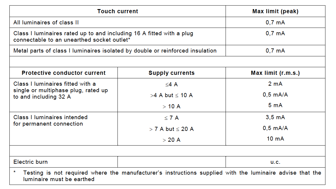
9.3 Touch Current, Protective Conductor Current and Electric Burn
The touch current or protective conductor current that may occur during normal operation of the luminaire shall not exceed the values given in Table
10) Creepage Distances and Clearances
This section specifies minimum requirements for creepage distances and clearances in luminaires.
The suitability is measured using tools such as calipers and gauges.
11) Endurance Test and Thermal Test
11.1 Endurance Test
Under conditions that represent heating and cooling in the areas of use of luminaires, the luminaire should not become dangerous or malfunction prematurely. Compliance with this rule is accomplished by the following experiment;
- Armature is placed in the oven with an ambient temperature of 25 ° C.
- The luminaire is tested for a total of 168 hours, consisting of 7 consecutive cycles of 24 hours in the housing. The supply voltage specified below is applied to the luminaire for the first 21 hours and the luminaire is "disabled" for the remaining 3 hours of each cycle.
- For fixtures with filament lamps during the working periods, the supply voltage other than ELV should be 1.05 ± 0.015 times the voltage from which the rated lamp power is obtained. The supply voltage for other luminaires should be 1.10 ± 0.015 times the maximum value of the rated voltage or the rated voltage range.
After the test, the component parts of the rail and rail system should be visually inspected in the armature as well as in the fixtures mounted on the rail. No part of the luminaire should be unable to function and no deformation should occur in the plastic ES lampholders. The luminaire should not become unsafe and should not cause damage to the rail system. Markings on the luminaire should be readable.
11.2 Thermal Test (Normal Operation)
Under normal operating conditions, no part of the luminaire (including the lamp), supply cables or mounting surface in the luminaire should reach a temperature that may impair safety. Compliance with this rule is accomplished by the following experiment;
- The ambient temperature is tested between 10 ° C and 30 ° C, preferably at 25 ° C, in the enclosure protected against airflow.
- Test voltage, luminaires with filament lamps other than ELV: Voltage that generates 1.05 times the rated power of the test lamp, excluding lamps (HTS), which must always be operated at the voltage marked on it. For other luminaires: 1.06 times the maximum value of the rated voltage or rated voltage range. Motor-containing luminaires: 1.06 times the rated voltage (or the maximum value of the luminaire's rated voltage range).
- The experiment continues until the armature becomes thermally stable (in other words, the temperature change rate is below 1 ° C per hour).
- Measurements are made by attaching thermocouples to the relevant parts of the luminaire.
The measured temperatures of the luminaire should not exceed the limits specified in the standard.
11.3 Thermal Test (Abnormal Operation)
Under conditions representing unusual operating situations (where applicable, but not representing a malfunction or misuse in the luminaire), the sections of the luminaire and the temperature of the mounting surface should not rise to extreme values and the connection inside the luminaire should not become insecure.
12) Screws and Connections
The screws used in joining the parts of the devices and electrical connections must be resistant to mechanical forces. Suitability is tested by tightening and loosening the screws at the moments given in the standard according to the thread diameters.
13) Resistance to Heat , Fire and Tracking
The outer sections of the non-metallic material, the sections made of insulating material that support the energetic sections, including connections, must be heat resistant. To verify compliance, ball pressure test, glow wire test, CTI test and needle flame test are performed at the values specified in the standard.
14) Screw Terminals
In this section, all of the screw terminal types embedded in the fittings must meet the relevant rules required by the standard.
15) Screwless Terminals and Electrical Connections
In this section, the cross-section areas used in the internal wiring of the luminaires and in the external wiring connection
For solid or braided copper conductors up to 2.5 mm2, the rules regarding all electrical connections and connection types are not specified.
TS 8698 EN 60598-2-1 / IEC 60598-2-1
Luminaires - Part 2-1: Particular requirements - Fixed general purpose luminaires
This part of IEC 60598 specifies requirements for fixed general purpose luminaires for use with electric light sources on supply voltages not exceeding 1 000 V.
TS EN 60598-2-2 / IEC 60598-2-2
Luminaires - Part 2-2: Particular requirements - Recessed luminaires
IEC 60598-2-2:2011 specifies requirements for recessed luminaires incorporating electric light sources for operation from supply voltages up to 1 000 V. This section does not apply to air-handling or liquid-cooled luminaires. This third edition cancels and replaces the second edition published in 1996 and its Amendment 1 (1997), of which is constitutes a technical revision. The changes introduced by this new edition are those required to maintain consistency later versions of IEC 60598-1 that have been published since the previous edition of this standard.
TS 8700 EN 60598-2-3 / IEC 60598-2-3
Luminaires - Part 2-3: Particular requirements - Road and Street Lighting
IEC 60598-2-3:2002+A1:2011 specifies requirements for:
- luminaires for road, street lighting and other public outdoor lighting applications;
- tunnel lighting;
- column-integrated luminaires with a minimum total height above normal ground level of 2,5 m;
- and for use with electrical lighting sources on supply voltages not exceeding 1 000 V.
TS EN 60598-2-4 / IEC 60598-2-4
Luminaires - Part 2-4: Particular requirements - Portable General Purpose
IEC 60598-2-4:2017 specifies requirements for portable general purpose luminaires for indoor and/or outdoor use (e.g. garden use), other than handlamps, designed to be used with or incorporating electrical light sources on supply voltages not exceeding 250 V.
TS EN 60598-2-5 / IEC 60598-2-5
Luminaires - Part 2-5: Particular requirements - Floodlights
IEC 60598-2-5:2015 specifies requirements for floodlights for use with electrical light sources on supply voltages not exceeding 1 000 V. This third edition cancels and replaces the second edition published in 1998, and constitutes a technical revision. This edition includes the following significant technical changes with respect to the previous edition: it introduces requirements for the glass breaking test.