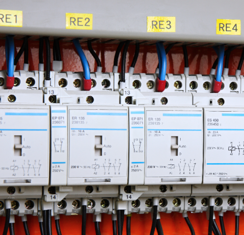
IEC / EN 60947 STANDARD
(Low Voltage Switchgear and Controlgear)
(Part 1: General rules)
The switchgear and controlgear type test is used to ensure the consistency of all the rules and features applicable to the low voltage control device and switching arrangement as much as possible, in order to obtain a regularity in the rules and tests throughout the relevant range of the equipment and to prevent the need to be tested according to different standards. Type testing is done in independent accredited laboratories. For all types of low voltage switchgear and control devices, only two essential documents are required to determine all rules and tests:
- The basic standard referred to as “IEC / EN 60947-1” in special standards covering various types of low voltage switchgear and control devices,
- The relevant privte standard, hereinafter referred to as the "relevant product standard" or "product standard".
The following sections are provided for the configuration of the IEC / EN 60947 standard series:
a) IEC / EN 60947-1: General rules,
Scope: Declared voltage 1000 V a.a. or equipment intended to be connected to circuits not exceeding 1500 V d.a.
IEC / EN 60947-2: Part 2: Power switchgear and controlgear assemblies.
IEC / EN 60947-3: Part 3: Switches, disconnectors, disconnector switches and fuse combination units.
IEC / EN 60947-4-1: Part 4: Contactors and motor starters.
IEC / EN 60947-5-1: Part 5: Circuit control devices and switching elements.
IEC / EN 60947-6: Part 6: Multifunctional switching devices.
IEC / EN 60947-7: Part 7: Auxiliary equipment.
When the IEC / EN 60947-1 standard type test is applied, it should be performed to verify compliance with the rules described in this standard and the relevant product standard.
These tests are given below:
- Type test to be applied to samples representing each special equipment,
- Routine tests applied to each individual piece of equipment made in accordance with this standard and related product standard, when applied,
- Sample tests when required in the relevant product standard.
The above tests may consist of a series of tests that comply with the relevant product standard rules.
The IEC / EN 60947-1 Type test consists of verifying the following:
Constructional requirement,
Temperature rise,
Dielectric properties,
Ability to make-carry-break currents,
Ability to make-carry-break short circuit currents,
Rated and limiting values,
Working performance,
Protection degree of enclosure ,
EMU tests.
1. Compliance with construction rules
1.1.Material description
Abnormal heat and fire resistance test
1.1.1.1. Glow wire test (applied to material):
A glow wire test is carried out to verify the suitability of the materials in the sections of the equipment or the sections taken from these sections.
2. Mechanical properties of the terminals:
This test does not applied to aluminum terminals or terminals used for the connection of aluminum conductors. Tests are carried out with the appropriate type of conductor with the largest cross-sectional area. The conductor is connected and disconnected five times. Screw-type connections are tightened with the appropriate tightening torques given in the standard. During the test, clamping units and terminals should not come loose. Screws should also not be damaged in crevices, threads and washers. These tests also include tensile and bending tests.
3. Verification of the position display efficiency of the main contacts of the equipment suitable for separation:
Equipment suitable for separation should provide a separation distance that provides sufficient separation function in the open position.
The position indicator of the main contacts must be provided with one or more of the following schemes:
- The position of the actuating element,
- A separate mechanical indicator,
- Visibility of moving contacts.
All arrangements showing the contact position should continue to function correctly after working performance type tests and special life tests, if any.
4. Temperature rise:
Temperature measurements are made in the rated current and frequency of the main circuit, auxiliary circuits and control circuits.
The measured frequency values should not exceed the limits given in the standard.
5. Dielectric properties:
The test is carried out to verify that the hardware can withstand the voltages stated below.
- Declaration impulse withstand voltage in accordance with the overvoltage category (4.3.1.3),
- Impact resistance voltage applied between the contact ranges of devices suitable for separation,
- Network frequency withstand voltage.
Whether there is any electrical puncture, superficial jump, electrical jump, puncture and destructive discharge during the experiment is verified.
6. Sample tests to verify the insulation intervals:
The insulating ranges are verified for their adequacy to be able to withstand the declared impact withstand voltage.
On the other hand, it is verified that the surface leakage path lengths are not smaller than the standard lengths in the measurements made depending on the degree of contamination of the equipment.
7. Making and breaking capacities:
It is verified whether the strucure is capable of breaking and making the load and overload currents without faults under the conditions and number of operations specified in the relevant product standard for the required usage categories.
8. Working performance ability:
The mechanical and electrical life tests of the hardware are also performed in the conditions given in the relevant product standard. Life tests are foreseen to verify the number of operating cycles that a hardware is capable of operating without repairs or replacing partitions.
9. Performance in short circuit conditions:
It is verified whether the hardware is able to withstand the thermal, dynamic and electrical stresses resulting from short circuit currents under the conditions specified in the relevant product standard.
10.EMU test
10.1.Immunity:
It is verified whether the equipment with electronic circuits has sufficient immunity against electromagnetic disturbances.
Structure with all passive circuits does not need to be tested.
10.2.Emission:
For equipment without electronic circuits, electromagnetic disturbances can only be produced during occasional switching operations. The duration of the distortions is in milliseconds.

